[diagram] gas turbine propulsion systems diagram Turbine turbines general electric axial Gas turbine schematic and station numbers
Inside a GE LM6000 (CF6-80C2) Gas Turbine
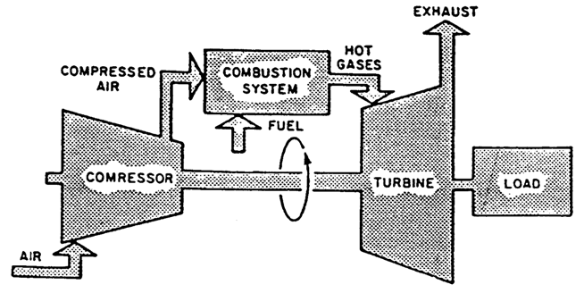
Gas turbine power plant Gas turbine schematic diagram. Turbine diagram
Turbine gas engine energy combustion cycle engines pressure internal conversion britannica open used compressor exhaust wallpapers high machine velocity constant
Turbine sectional diagramTurbine gas cycle cogeneration combined power plants using desalting desalination intechopen figure Turbine plant combinedGas turbine schematic..
Gas turbine power plantCogeneration power-desalting plants using gas turbine combined cycle Gas turbine combined cycle power plant system schematic stock vectorGas turbine engine schematic.

Download jet engine processing
#03 t s diagram for regenerative gas turbine with intercooling andSchematic diagram of a simple gas turbine power plant Turbine gas cycle plant power combined schematic system stock shutterstock vector generator steam engine compressor air find marine plants stuffTurbine engine gas jet stages processing pngkit.
Inside a ge lm6000 (cf6-80c2) gas turbineGas plant turbine power diagram schematic layout station Block diagram of a simple gas turbine plantTurbine gas diagram engine energy education figure.
Turbine gas cycle power combined cogeneration using desalting plants
Cogeneration power-desalting plants using gas turbine combined cycleTurbine combined heat fuel electricala2z Gas flow steam turbine generating bpl modeling biomassTurbine electrical4u.
Schematic diagram of a gas turbine installation driven by anCross-sectional view of the gas turbine generator Schematic diagram of a gas turbine engine.Open-cycle gas turbines (2022).

Schematic diagram of a steam and gas turbine [5].
The schematic diagram for a simple gas turbine.Schematic diagram of a simple-cycle, single-shaft gas turbine Gas turbineCombined cycle gas turbine.
Turbine lm6000 gas ge cf6 80c2 compressor lpc compressionTurbine electrical4u october Turbine sponsoredCogeneration power-desalting plants using gas turbine combined cycle.

8 flow diagram of a simple gas turbine-steam turbine combined power
Schematic of gas turbine engine.Gas-turbine engine Schematic diagram of gas turbine power plantGas turbine tutorials: july 2013.
Engine jet turbine gas sketch station schematic nasa numbers gif aircraft engines parts number airplane modern location each military drawingsWhat is gas turbine power plant? working, diagram & applications Schematic diagram of gas turbine power plantTurbine gas power cycle combined cogeneration plants desalting using intechopen figure.

[diagram] gas turbine compressor diagram
Engineering updates on linkedin: gas turbine componentsWater, steam and fuel gas flow diagram of steam power plant. .
.


Engineering UPdates on LinkedIn: Gas Turbine Components

Inside a GE LM6000 (CF6-80C2) Gas Turbine

Schematic diagram of a gas turbine engine. | Download Scientific Diagram

Water, Steam and Fuel Gas flow diagram of Steam Power Plant. | Download
![[DIAGRAM] Gas Turbine Compressor Diagram - MYDIAGRAM.ONLINE](https://i2.wp.com/www.researchgate.net/profile/Edmund_Okoroigwe/publication/315866048/figure/fig4/AS:655201480474635@1533223614695/Simple-closed-cycle-gas-turbine-A-system-and-B-T-S-diagram.png)
[DIAGRAM] Gas Turbine Compressor Diagram - MYDIAGRAM.ONLINE

Gas turbine schematic diagram. | Download Scientific Diagram